Welcome to Flightinfo.com

  • Register now and join the discussion
  • Friendliest aviation Ccmmunity on the web
  • Modern site for PC's, Phones, Tablets - no 3rd party apps required
  • Ask questions, help others, promote aviation
  • Share the passion for aviation
  • Invite everyone to Flightinfo.com and let's have fun

Question Avionics Circuit Breaker Switch Fail

Welcome to Flightinfo.com

  • Register now and join the discussion
  • Modern secure site, no 3rd party apps required
  • Invite your friends
  • Share the passion of aviation
  • Friendliest aviation community on the web
I ordered spare push pull breakers from CubCrafters. Price was reasonable. The 50A breaker is $315!!! So that's a no for me for the spares kit.
 
I realize I probably missed the ignition breakers on the front of the seat which I believe are 40A's? Doubt I'll get anymore, have what I have for now.
 
I was wrong, the ignition breakers forward of the seat are 5A.

Opened my package from CubCrafters and the packaging for breakers is all aircraft spruce so just buy direct from them.

IMG_6931.JPG
 
Many years ago a friend of mine blasted off out of KBFI in a rented Mooney 201 into the overcast. After getting radar contact with departure and a getting on course the entire radio stack died…in actual IFR conditions-the master CB Switch had tripped.

After extracting a bunch of seat cushion from his nether regions and a few unsuccessful reset attempts all of the radios were turned off and the avionics master successfully reset with no load. In a trial and error method radios were turned back on and it was determined that one nav/com with no GS receiver would not trip the master-anything more and Still, no xpnder, no DME, no ADF (it was a while back!), no second nav/com and no precision approach capability!

After re-establishing contact with SEA and declaring my friend got vectored around and pointed back to BFI which fortunately wasn’t that bad-about a thousand and 2 or so and he got back in okay on a localizer approach.

In an effort to learn from the experience of others, when I set up an IFR panel back in the day I had two Master Avionics switches installed in parallel. In order to ensure continued redundancy I would use one on odd numbered days and the other on even number days.

There is little enough redundancy in a single engined airplane and to expose yourself to a single point failure of that kind is an easy fix with almost no cost in weight.
 
I understand that most Garmin LRUs can accept multiple power sources, and I further understand that the IBBS can be connected to more than one device.

While some Garmin LRU have 2 independent power inputs I doubt it is true that "most" Garmin LRU have two independent power inputs. GPS 175 (and family) do not, GTX 345R does not, GAD 29 does not, GMC 305 does not, GSA 28 servos do not, G5 does not (but does have independent battery backup option).

In the CC Exec Glass aircraft IBBS powers GDU 465, GSU 25C (feeds GMU 22), and GEA 24. A good IBBS battery will power these for 2 hours or more. Adding loads would reduce that but, if load does not have independent power inputs, additional power switching would be required.

The standard Exec Glass Avionics switch breaker is 10 A and I suspect it is barely adequate. Very surprised that CC did not increase the rating for the IFR fit.

Does the Avionics switch need to be a breaker type? Each avionics LRU has its own CB.

If you are concerned about loss of everything on the Avionics bus then consider two independent Avionics switches. How would you decide which LRU to put on Avionics-1 and which on Avionics-2. You have likely have only one audio panel, one transponder, and one IFR GPS.

I don't have the audio panel in my IFR capable FX-3. I could rig an alternate power source for the GTR 200 but it's not high on the list of priorities.
 
The standard Exec Glass Avionics switch breaker is 10 A and I suspect it is barely adequate. Very surprised that CC did not increase the rating for the IFR fit.
CC G3X Schematic shows the Avionics switch breaker as 10 A.

CC schematic -103 CC11-160 POWER DISTRIBUTION AND START CIRCUIT shows a 20 A Avionics switch breaker. This schematic is listed as applicable to the FX-3.

The equivalent schematic in the maintenance manual template is of too low a resolution for the CB rating to be read clearly but I think it is 20 A.
 
Many years ago a friend of mine blasted off out of KBFI in a rented Mooney 201 into the overcast. After getting radar contact with departure and a getting on course the entire radio stack died…in actual IFR conditions-the master CB Switch had tripped.

After extracting a bunch of seat cushion from his nether regions and a few unsuccessful reset attempts all of the radios were turned off and the avionics master successfully reset with no load. In a trial and error method radios were turned back on and it was determined that one nav/com with no GS receiver would not trip the master-anything more and Still, no xpnder, no DME, no ADF (it was a while back!), no second nav/com and no precision approach capability!

After re-establishing contact with SEA and declaring my friend got vectored around and pointed back to BFI which fortunately wasn’t that bad-about a thousand and 2 or so and he got back in okay on a localizer approach.

In an effort to learn from the experience of others, when I set up an IFR panel back in the day I had two Master Avionics switches installed in parallel. In order to ensure continued redundancy I would use one on odd numbered days and the other on even number days.

There is little enough redundancy in a single engined airplane and to expose yourself to a single point failure of that kind is an easy fix with almost no cost in weight.
Very good information, thank you. This is exactly the reason why I'm not going put up with this being a single point of failure.
 
This is exactly the reason why I'm not going put up with this being a single point of failure.

Everything that is on the Avionics bus will go away if the Avionics switch fails, or if the master contactor or its wiring fails, or if the Master switch fails. The Avionics bus will likely be shed if the alternator fails so that battery capacity is retained to keep the engine running.

Eliminating single point failure of the Avionics bus powered equipment requires more thought than just considering the Avionics switch.

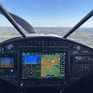
If Avionics power fails, or if all Master power fails, I still have GDU PFD and ND and a G5 as backup. What I'll likely miss most is COM and secondly the Autopilot.

If/when I install my GTR 20 remote COM I may consider putting my GTR 200 on a different power source or add switching to manually select an alternate power source.

I have also been considering manual RS-232 bus switching so the G5 and GMC can give me AP after the GDU fails.

Failure of the GDU 465 may be far more debilitating than loss of the Avionics bus.
 
@Cactus Charlie thank you for the opportunity to bounce this around with you! Would appreciate your thoughts on the following:

1) GDU 465 failure would indeed be majorly problematic. However, with my panel, the GDU 465 is powered by the IBBS if the Master fails. I suppose there's a risk that the GDU itself fails leaving me with the G5 only, but not sure there's much I can do about that.

2) How is the G3X's internal GPS (not IFR certified) powered? If Master loses power, will the internal GPS work via the GDU 465 being powered through IBBS?

3) I spoke to an avionics tech yesterday and he also concluded that a 10A avionics CB switch is marginally inadequate. He also observed that all avionics units are protected with their own dedicated circuit breakers. He suggested moving up to 20A CB avionics switch, or even converting to a standard switch. What's your view between those two options?

4) What would be involved in installing an additional independent avionics switch in parallel with the current switch? My current panel does not have a blank, unused space for an additional switch. Can an additional switch basically be added wherever I can find space?

5) If a second Avionics switch was installed, in your opinion would this be sufficient redundancy to then not worry about further redundancy such as additional IBBS connections?

6) As I think about what minimum IFR equipment I would really not want to lose in IMC, it's the GDU 465, the GNC 355 (which gives me one radio) and the GMA 245R audio panel. This would mean losing the second radio and the transponder - which wouldn't be great but doable. The GDU 465 is already connected to the IBBS. You mentioned above that the GNC 355 and GTX 345R cannot accept an IBBS backup power source. Can the GTR 20 and the GMA 245R accept IBBS back up power? If answer is no, is there any other creative solution for powering LRUs that were not built to accept IBBS backup power if the avionics bus is deenergized?
 
1) GDU 465 could fail because of a hardware fault or because of a software defect. I heard of one Garmin update that caused continuous GDU reset under a specific set of conditions. I don't have any detail but it was probably over 5 years ago.

2) Everything, including the internal VFR GPS, works when GDU is powered by IBBS. The two power sources are "diode or'd" which means the higher voltage is used. IBBS outputs are not enabled unless IBBS input voltage is lost.

3) I ran a quick test yesterday and the avionics current draw was about 5 A with GTR 200 transmitting but not modulated. AP was not engaged so servo load not included. I don't have the remote audio panel. Always remember that circuit breakers are sized to protect the wiring not to protect the powered equipment. The Avionics switch breaker protects the link from MAIN Bus to the Avionics switch. That link is wire MB11A12R which should be 12 AWG. If the Avionics switch /breaker was replaced by a plain switch then a short at the Avionics bus bar would likely blow the Main bus 40 A fuse if the link didn't burn out first. I have not done any analysis of all the possible failure modes of the electrical system and won't make any recommendation on changes to it.

4/5) If you are really concerned about Avionics switch/breaker failure you could wire a second one in parallel. There are more critical single point failures in a Carbon Cub than the Avionics switch/breaker.

6) The GTR 20 is the same radio as the GTR 200 except that panel is not present. It does not have redundant power inputs. I have not looked at the audio panel. Redundant power can be provided to any LRU by using two external diodes, one in series with each power source. The GTR 20 is not the radio that should have redundant power. It can't be controlled if the GDU 465 fails. I don't know if the remote audio panel provides a direct pass through if it is unpowered. You would need to research whether it does "pass through" and, if so, which COM radio is still usable when the audio panel is not powered. I would hope it is designed to "pass through" COM 1 and that redundant power on the GNC 355 would be the right choice.

For lost COM in VMC or IMC there is always the possibility of Bluetooth from phone direct to headset if batteries are fitted or available to be fitted.

This is all "off the cuff" and just to keep a conversation going.
 
Last edited:
@Cactus Charlie , again really appreciate the discussion.

1) Understood, so far so good with my GDU.

2) Very good to know.

3) Very good comments. I think I'll upsize to a 15A CB switch and monitor.

4/5) OK I'll take the bait. In your opinion what are the critical "single points of failure" in the CC IFR panel? I definitely intend to fly the plane IFR and am interested in what modifications can be done to add redundancy and address failure modes? Adding a second Avionics CB switch seems like a good start, but if I'm gonna go down this path working with an avionics shop to make changes, I'd like to address everything that I can in one trip to the shop.

6) Excellent observation, I'm researching now. If it turns out that the GMA 245R has "pass through" capability and Com1 can be wired to that pathway, then I'm definitely going to look into redundant power for the GNC 355.

All this discussion of failure scenarios has also convinced me that I need to come up with a solution to be able to keep a hand-held radio within reach at all times. Currently, by hand-held is in my flight bag in the aft cargo area ... pretty much useless in an actual situation when it's needed.
 
I had not intended to limit single point failures to the avionics. No single point failure of the avionics is an immediate threat to my safety even in IMC.

If I had to pick an avionics concern it would be Garmin's current design for reversion to alternate attitude data. It takes well over 10 seconds for a reversion to G5 data if the GSU 25C malfunctions and provides misleading attitude data. Keep that G5 in your scan.

Yes, a handheld radio is a useful backup but only if the headset can be connected to it.
 
Last edited:
Agree, my hand-held has a direct LEMO plug receiver.
 
@Cactus Charlie I've confirmed that the GMA 245R has a "fail safe" path that provides for a pass through of COM1 when the unit is deenergized. Thus, your idea of providing backup power to the GNC 355 is a great one. What's the process for doing that given that it's not designed to accept a second power source?
 
Backup power for GNC 355:

First decide on your backup power source.

If you decide on a second IBBS the implementation is quite easy. The IBBS can be configured to pass power through when it is available and to switch to backup power when external power is not available. Only a single power feed from the new IBBS to GNC 355 would be required. (Note that the existing IBBS installation does not work that way as pass through power is not implemented).

If I added a second IBBS it would be used for emergency ignition. I consider the existing AGM emergency ignition battery to be inadequate and plan to use main battery for ignition as long as possible keeping the AGM battery as a desperate lost resort. Perhaps you need 3 IBBS to reach your desired comfort level.

Solutions that do not use a dedicated Avionics IBBS may be harder to implement. You don't want to use MAIN bus or battery direct to power the GNC 355 unless it is a manually switched reversion. GNC 355 should not be powered during engine start.

The existing IBBS will not enable backup output unless IBBS switch is on and the charging input is lost (MAIN bus). It doesn't know or care if Avionics bus is live. However, it is possible to force the enabling of IBBS backup power simply by pulling the IBBS circuit breaker.
 
Not likely enough room for a new IBBS behind the instrument panel. Will it work to install a new (third) IBBS in the aft avionics bay, run wires up to the panel, charge the IBBS from the avionics bus, and connect the back-up power to the CB driving the GNC 355? Would the new IBBS require its own switch? Related question, if I'm going to this trouble to dig into the panel, does it make sense to upgrade the existing IBBS batteries from 3AH to 6AH? I realize there's a cost to this, but it may be worth it to double the time available to work through an electrical failure.

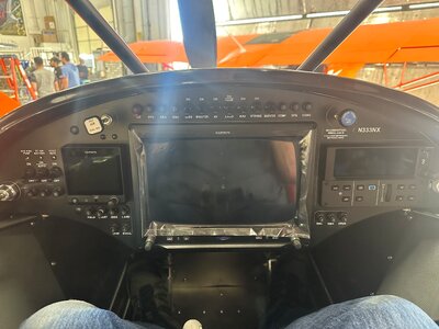
Pic of panel layout below. Really appreciate this discussion.
 

Attachments

  • N333NX Panel.jpg
    N333NX Panel.jpg
    1.5 MB · Views: 2
I took another look at the TCW IBBS manual. It requires pass through power input pins to use the same source as the charging input. Since you want GNC 355 to be on Avionics bus for normal operation it means that the new Avionics IBBS must be charged from Avionics bus. This puts up to 2.5 A additional load on the Avionics bus switch/breaker.

If also means that GNC 355 would receive power from the Avionics IBBS whenever it was enabled and Avionics bus was not live. You would have to, by procedure, only enable Avionics IBBS after you would turn on Avionics bus.

Its easy to go down a rabbit hole.
 
Already have two IBBS batteries. One for the (R) IGN electronic ignition (see switch / CB on the left) and one IBBS that presently drives only the GDU 465 (best I can tell) activated by the IBBS switch top row and having a 5A circuit breaker below the G5. These are identical 12V 3AH batteries.
 
Is the ignition IBBS now a CubCrafters option or it is something you specified yourself? Either way, much better than the AGM battery.

My IBBS discharge test showed over 2 hours operation of G3X touch system. I see no need for longer but a periodic discharge test is required to confirm capacity.

edit to add - Standard IBBS does not just drive the GDU 465. I gave the list of LRU earlier in the thread.
 

Latest resources

Back
Top