lrobichaux
FI Supporter
- Joined
- Apr 20, 2025
- Posts
- 168
- Type aircraft owned
- SR-22T / CCrafters EX-3 and NXCub
- Base airport
- KADS
- Ratings
- PPL, IR
Update to a previous post that I was considering some avionics upgrades after my avionics CB switch failed. Here is what I had done, and the results:
1) upgraded the avionics bus CB switch from 10A to 15A (shop determined that the existing wiring was sufficient to handle the amperage increase)
2) added a second dedicated back-up avionics power circuit with its own 15A CB switch (in case there's an in-flight CB switch failure like I experienced a couple of months ago)
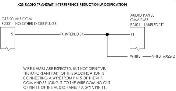
3) installed a COM1 interlock tie-in as prescribed by CubCrafters to address static in my headset when transmitting and also monitoring both COM1 and COM2
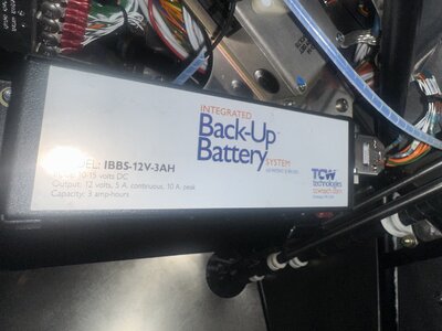
4) upgraded the right ignition IBBS from a 3 amp-hour battery to a 6 amp-hour battery
Tech Aero based at KDTO did a fantastic job. Everything works as desired.
If anyone wants information on #3 above, reach out to Pete or I'm happy to provide information. More importantly, if anyone can make good use of a nearly-brand-new 3 amp-hour IBBS battery, first one to respond in the affirmative below I'll gladly package it up and send to you - no cost. I just want someone to get some use from it, as it's just gonna otherwise sit in my hangar and eventually become unserviceable. It's a TCW IBBS-12V-3AH for experimental installs. Does not have the install harness as that was needed for my upgraded battery.
1) upgraded the avionics bus CB switch from 10A to 15A (shop determined that the existing wiring was sufficient to handle the amperage increase)
2) added a second dedicated back-up avionics power circuit with its own 15A CB switch (in case there's an in-flight CB switch failure like I experienced a couple of months ago)
3) installed a COM1 interlock tie-in as prescribed by CubCrafters to address static in my headset when transmitting and also monitoring both COM1 and COM2
4) upgraded the right ignition IBBS from a 3 amp-hour battery to a 6 amp-hour battery
Tech Aero based at KDTO did a fantastic job. Everything works as desired.
If anyone wants information on #3 above, reach out to Pete or I'm happy to provide information. More importantly, if anyone can make good use of a nearly-brand-new 3 amp-hour IBBS battery, first one to respond in the affirmative below I'll gladly package it up and send to you - no cost. I just want someone to get some use from it, as it's just gonna otherwise sit in my hangar and eventually become unserviceable. It's a TCW IBBS-12V-3AH for experimental installs. Does not have the install harness as that was needed for my upgraded battery.
") I may reach out to Pete to get my name on the list and also verify my install is subject to the same issue and will keep this thread updated should I do anything. I'm getting ready to head out in my motorhome for a bit so it may not be until later when I'm ready to screw something up again
I may reach out to Pete to get my name on the list and also verify my install is subject to the same issue and will keep this thread updated should I do anything. I'm getting ready to head out in my motorhome for a bit so it may not be until later when I'm ready to screw something up again 


