Welcome to Flightinfo.com

  • Register now and join the discussion
  • Friendliest aviation Ccmmunity on the web
  • Modern site for PC's, Phones, Tablets - no 3rd party apps required
  • Ask questions, help others, promote aviation
  • Share the passion for aviation
  • Invite everyone to Flightinfo.com and let's have fun

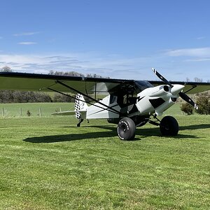
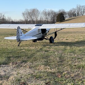
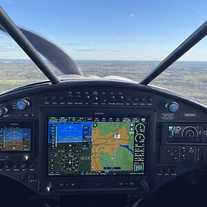
Avionics Work on my NXCub

Welcome to Flightinfo.com

  • Register now and join the discussion
  • Modern secure site, no 3rd party apps required
  • Invite your friends
  • Share the passion of aviation
  • Friendliest aviation community on the web
Tonight's flight I tried having both COM 1 and 2 enabled with MIC 1 active. I definitely get feedback, albeit slight, when transmitting. When I turn off COM 2 it's crystal clear.

Let me know how your change works. Also, are you doing this wiring yourself or having an avionics tech do it?
I had an avionics shop do it. Did you try the same test with MIC2 active with both COM1 and COM2 enabled? I'm going to do a proper test this weekend and load up the video results here.
 
Did you try the same test with MIC2 active with both COM1 and COM2 enabled?
No, it was just a quick test of "do I have the issue" and then just went on my way from there :) I may reach out to Pete to get my name on the list and also verify my install is subject to the same issue and will keep this thread updated should I do anything. I'm getting ready to head out in my motorhome for a bit so it may not be until later when I'm ready to screw something up again :)
 
I reached out to Pete and he provided me the attached PDF. It seems there's an earlier option of changing the dip switch on the GMA 245R before making a wiring change. Have you tried this option yet @lrobichaux?

It's not a critical issue but I'm open to making this better as the feedback when transmitting is distracting and concerning albeit minimal, but it's there.
 

Attachments

Last edited:
That more complete write up makes it appear that GTR 20 (COM 2) pin 5 is not wired before the mod.

The correct way to de-sense COM 2 is to correctly wire the TX Interlock (2 wires between COM 1 and COM 2). The TX Interlock should be independent of the audio panel wiring. It is simply COM 1 interlock out to COM 2 interlock in, and COM 2 interlock out to COM 1 interlock in.

Didn't CC provide the schematic for the "as delivered" configuration of dual COM aircraft?
 
Umm, does anyone get schematics other than what's in the AMM? It may be in the EX kit manuals but I haven't and don't plan to hunt for it. COM1 is up front, COM2 and GMA 245R are over the rear seat. Would not be fun wiring.

What is your opinion on the #3 dip switch? I plan to give that a try.
 
The schematics in the current AMM do not cover the dual COM installation. They are low resolution copies of the schematics applicable to the basic Exec Glass configuration (No IFR GPS and single GTR 200 as COM 1). I created my own schematics for the addition of the G5 and GPS 175 to my FX-3.

I did some more research and it appears that the GNC 355 has no TX interlock capability. That was very surprising since it is provided on the GTR 20 and GTR 200 radios.

I would expect that COM 1 PTT could be used to drive COM 2 "TX Interlock In" and that may be what the CC mod is intended to do.

I can see no way to de-sense COM 1 when COM 2 is transmitting.
 
You didn't comment about the dip switch :)

So I went to the plane, toggled dip switch 3 and did some com tests within the hangar. Both COM1 and COM2 transmit were clean. I don't know if there are any side effects I'm not aware of with this dip switch change but so far it seems good.
 
I'm confused! I think ALL dip switches on the unit are in the ON position. Per the manual, that shouldn't be the case. The unit is mounted with the bottom of the unit to the ceiling, all dip switches are towards the top of the unit so I believe that means they are all ON??? If I can't determine on vs. off I'll just put mine back the way it was. Too confusing and doesn't seem to be set per the manual which may be part of the overall problem.

dip-switches.jpg
 
It seems unlikely that the switches would be all ON since the default case is all OFF and CC suggested changing 3 to ON.

It would have been easier if Garmin had marked ON/OFF and the switch numbers on the chassis as I expect the marking on the DIP switch itself is concealed.

I have never seen the remote audio panel but an 8 way DIP would usually have switch 1 on the left and up would be ON. See DIP switch - Wikipedia

However, Garmin says "Per the label attached to the top cover of the unit, the down switch position is ON, the up switch position is OFF."

A call to Garmin support and subsequent marking of the chassis may be in order.

Reminds me of an big airplane program I was working on where one subsystem group decided ground/open discretes should be interpreted in the opposite sense to the interpretation used by every other subsystem.
 
BTW you don't seem to have the latest version of the GMA installation manual.

DIP 5 is allocated - "When set to ON, the Pilot and Copilot have a dedicated PTT key for each COM radio. This allows a crew member to select a COM for transmit using the dedicated PTT key for the radio. Requires software version 3.20 or later." (Ref rev 13)
 

Latest resources

Back
Top