- Joined
- Oct 31, 1996
- Posts
- 1,360
- Type aircraft owned
- Carbon Cub FX-3
- Base airport
- KFCI
- Ratings
- COMM, IFR, MEL, SEL
While I'm still testing the EarthX backup battery as outlined in this thread, I'll start a thread for those considering use of the TCW IBBS 3AH LiFePO4 battery. I welcome discussion on wiring required for a EX-3/FX-3 which the factory uses a 12V AGM battery, typically the PowerSonic P1221S which is a 2AH battery.
Items required:

 www.tcwtech.com
 www.tcwtech.com
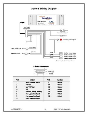
The FX-3 has a two position emergency ignition switch OFF/ON.
From my high level overview and not looking at the current schematic of the ignition backup circuit, hopefully someone can post that, it seems the current incoming positive would go to PIN 5 and the ground PIN 9. However, the difference here is the OUTPUT of the IBBS battery goes out 6,7,8 so this would require some wiring change so that output goes to the Light Speed Ignition. I'm interested in how that's currently wired and what would need to be changed to effect this battery upgrade.
Open to discussion and share knowledge to help others that may be considering this option.
Light Speed diagram below, others and manual attached.

Items required:
Integrated Battery Back-up System (IBBS) - TCW Technologies
The Integrated Battery Back-up System (IBBS) provides an engineered solution to enable an endurance bus for critical loads found in aircraft. The IBBS system provides back-up power to critical electronic loads such as EFIS, GPS, Autopilots and engine monitoring systems.
www.tcwtech.com
IBBS Installation Wiring Harness w/mating DSUB Connector - TCW Technologies
Premade, color-coded wiring harness with mating D-SUB connector for Integrated Battery Back-up System (IBBS) units. Available models in: • 10' or 20' Length • Experimental or Certified units Please select your product options below.
www.tcwtech.com
The FX-3 has a two position emergency ignition switch OFF/ON.
From my high level overview and not looking at the current schematic of the ignition backup circuit, hopefully someone can post that, it seems the current incoming positive would go to PIN 5 and the ground PIN 9. However, the difference here is the OUTPUT of the IBBS battery goes out 6,7,8 so this would require some wiring change so that output goes to the Light Speed Ignition. I'm interested in how that's currently wired and what would need to be changed to effect this battery upgrade.
Open to discussion and share knowledge to help others that may be considering this option.
Light Speed diagram below, others and manual attached.