Welcome to Flightinfo.com

  • Register now and join the discussion
  • Friendliest aviation Ccmmunity on the web
  • Modern site for PC's, Phones, Tablets - no 3rd party apps required
  • Ask questions, help others, promote aviation
  • Share the passion for aviation
  • Invite everyone to Flightinfo.com and let's have fun

Alt Circuit Breaker Popped Twice Yesterday

Welcome to Flightinfo.com

  • Register now and join the discussion
  • Modern secure site, no 3rd party apps required
  • Invite your friends
  • Share the passion of aviation
  • Friendliest aviation community on the web
@Cactus Charlie see link below. I’m working to download the actual data file and will post that up too.


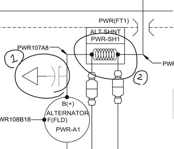
From what I can make of the numbers, I would have to guess that something caused a loss of alternator voltage regulation and then an overvoltage shunt somewhere tripped the breaker. The one-second sample rate on the logs would not be fast enough to capture the actual trip event.

I am not familiar with the xcub electrical system, but it looks as if you have a lead acid main battery that is not in great condition from the amount of main bus voltage drop when the alternator dropped offline. Does the AMM that comes with the Xcub have the wiring schematics in the back?
 
@lrobichaux - the coil packs are part of the electronic (light speed) ignition system but I have no clue what's used in your plane, and quite frankly, stop at I have no clue.

Any talk with Pete on a warranty replacement of the push-pull breaker? That's the most expensive one in the plane so I'd see if CC can send you one. It's rare but breakers do go bad too. Also check wires on the breaker. My IBBS wire came off the breaker which caused a 6 month hunt for the "IBBS in use" message on my G3X until I noticed a pink wire dangling one day looking under the panel. I found a screw on the floor which I saved and then the puzzle came together. So check the security of the wires at the breaker as well.
 
I am not familiar with the xcub electrical system, but it looks as if you have a lead acid main battery that is not in great condition from the amount of main bus voltage drop when the alternator dropped offline.
It has an EarthX ETX 900 vented LiFePO4. Seems to be in good shape, as I keep it connected to the proper battery tender.
Does the AMM that comes with the Xcub have the wiring schematics in the back?
CC has sent me all the wiring schematics.
I would have to guess that something caused a loss of alternator voltage regulation and then an overvoltage shunt somewhere tripped the breaker.
I'm not an electrical engineer, but your guess seems spot on to me. If this pattern repeats, I'll be filing a warranty claim for a new alternator.
 
I looked at the data and it is consistent with an intermittent short to ground of the alternator output . This short must be down path of the CB and current sensing shunt.

Of general interest - the NX (at least this NX) instruments alternator current, not battery current, so not the same as EX-3 or FX-3.
 
If this pattern repeats, I'll be filing a warranty claim for a new alternator.

Nothing wrong with the alternator but you may run up a few hours of labor if you pay someone to find the intermittent short circuit.
 
I looked at the data and it is consistent with an intermittent short to ground of the alternator output . This short must be down path of the CB and current sensing shunt.

Of general interest - the NX (at least this NX) instruments alternator current, not battery current, so not the same as EX-3 or FX-3.
Since my EIS instruments alternator current, does this mean that I do not need a Hall effect sensor like you described above? If correct, why do I not get a CAS message when the Field CB is pulled? Is this just a G3X EIS set-up issue?

Also, if the intermittent short is downstream of the CB, does this mean the voltage regulator cannot be the problem?
 
@Cactus Charlie what does the symbol next to #1 mean, and what does #2 do?
 

Attachments

  • IMG_1151.jpeg
    IMG_1151.jpeg
    209.9 KB · Views: 11
Since my EIS instruments alternator current, does this mean that I do not need a Hall effect sensor like you described above? If correct, why do I not get a CAS message when the Field CB is pulled? Is this just a G3X EIS set-up issue?

Also, if the intermittent short is downstream of the CB, does this mean the voltage regulator cannot be the problem?

For the Carbon Cub SS/EX/FX the alternator circuit looks like:

Screenshot 2025-12-20 at 17.02.43.png


You can see here the overvoltage "crowbar" that grounds the field if the field voltage is too high. This will blow the field breaker, which in turn then disconnects the alternator output via the "OV Relay". Remember that disconnecting the alternator from all loads without first disconnecting the field can cause really large voltage spikes that normally "let the smoke out" of something (such as the alternator's built-in regulator).

As you have an alternator "shunt" to measure the current somewhere in the XCub, there must be some changes in the alternator circuit from the SS/EX/FS to the XCub. Did you see the recent CubCrafters service notice about the XCub alternator?

 
The symbol next to 1 is an electrolytic capacitor. It is there to suppress alternator whine.

2 is the current shunt. It is a very low value resistor that passes the alternator current. There is a voltage drop across the shunt that is proportional to the current being passed. That voltage is sensed by the two lines below the shunt. The symbols in those two lines are fuses. After passing through the fuses the voltage is fed to GEA 24 and then displayed as current on the GDU.

You do not need to add a Hall effect sensor to read alternator current since it is measured by the shunt. If you wished you could add a Hall effect sensor to measure battery current. I like having alternator and battery current but it would only be useful to have both if you know how to interpret the data.

The electrical system of the NX is not the same as the EX/FX. Also, the X/NX schematics I have seen do not match the charging system of the aircraft under investigation. If it was my aircraft I'd be asking for the applicable revision of the DC power schematic.

All that said - I'm confident you have an intermittent short of the alternator output and it may not be easy to find. On my old PA-28 (now sold) I had an intermittent alternator short that was traced to the alternator wire fretting on the crankcase mounted support clamp. Over 40 years of vibration had worm through the rubber on the clamp and the insulation on the wire. Don't expect to find that sort of problem on a nearly new airplane.
 
why do I not get a CAS message when the Field CB is pulled? Is this just a G3X EIS set-up issue?

No idea how your alerting is configured. If you send, or post, a screen shot of the ALT AMPS scale definition I could answer your question.

In previous discussion you have said the ALT CB tripped or you pulled the ALT CB. The schematic shows no ALT CB. You now ask about pulling the FIELD CB.

All my comments on your problem have assumed the ALT CB tripped not the FIELD CB. The EX and FX have both.

Would you please post a photo of your panel showing the CB that tripped in flight and the CB(s) that you have pulled while investigating this problem.
 

I see no ALT CB in the panel picture, only a FIELD switch and FIELD CB. The panel picture also shows no alerting for alternator current zero.

I suppose it is possible for the FIELD CB to trip if the alternator output was shorted. The short would pull down the output voltage and the regulator would increase field excitation in an attempt to get the voltage back up.

I still believe there is an intermittent short on the alternator output as that is the only explanation I can see for the large spikes in alternator current.
 
High resolution pic of the panel. All CBs are in this picture. There are no CBs not on the main instrument panel.
 

Attachments

  • IMG_7604.jpeg
    IMG_7604.jpeg
    2 MB · Views: 18
Last edited:
Would you please post a photo of your panel showing the CB that tripped in flight and the CB(s) that you have pulled while investigating this problem.
Field CB popped. I do not have an Alt CB. See pic of the panel.
 
I assume you have a GMA 245R over the rear seat? There is a USB port on the front of it. Do you have anything plugged into that?

I had the FLD breaker pop once and it's the only time I ever used that USB port to try and power a GoPro.
 
Here is the FX-3 CB group. You can see the reason for the confusion caused by describing the field CB as the alternator CB.

FX-3 ALT CB.PNG
 
Hard to believe there is no ALT breaker but then again you have a larger ALT than us. I’m curious, what breakers are on the front of your seat base?
 
The schematic shows an alternator fuse not a CB.
 
There is a USB port on the front of it. Do you have anything plugged into that?
Remote audio panel is located in the aft avionics bay (which the FX-3 does not have). Nothing plugged into the USB power outlet.
 
As suggested in my email - start your visual inspection at the shunt.

If no problem found there you will have to inspect all the wiring between the shunt and the battery as well as the start and main solenoid connections.
 
Actually, there is one CB not on the main instrument panel. The left ignition CB. See attached.
 

Attachments

  • IMG_9278.jpeg
    IMG_9278.jpeg
    1.4 MB · Views: 11
If no problem found there you will have to inspect all the wiring between the shunt and the battery as well as the start and main solenoid connections.
I’ll update everyone what the avionics shop finds 😂😂. This is outside of my attention span and most likely skill level too.
 
I’ll update everyone what the avionics shop finds 😂😂. This is outside of my attention span and most likely skill level too.
Good call. I'm out of ideas and my skill level of suggestions. These are too complicated and I'm no A&P by a long shot. The planes have quite a bit of variance at least from the breaker setup. I hope someone finds it and you can regain peace of mind.
 
Also, the X/NX schematics I have seen do not match the charging system of the aircraft under investigation. If it was my aircraft I'd be asking for the applicable revision of the DC power schematic.

I'll retract that but I'm unable to delete it. It was based on the incorrect assumption that the aircraft under investigation had an ALT CB not the fuse shown in the schematic.
 
Schematic attached.

Now that I can see the schematic, it is interesting to see that they attempted to "simplify things" by switching to an external alternator regulator with built-in overvoltage protection rather than the SS/EX/FX, which has an alternator with a built-in voltage regulator and an external overvoltage protection system. I have several concerns about how they wired the external regulator in, but that is really for another time.

From the technical overview of the external regulator, it is clear that the voltage regulator became unstable, and that triggered the overvoltage protection to trip the field breaker. The regulator claims to be a "linear voltage regulator" design that should prioritize stability over efficiency, so either the regulator internally failed in some way, or more likely had external noise injected from a poor connection. I would carefully inspect all wire terminations to and from the regulator and alternator, as one or more appear to be loose and/or corroded.
 
From the technical overview of the external regulator, it is clear that the voltage regulator became unstable, and that triggered the overvoltage protection to trip the field breaker.

Did you look at the flight log for the "normal" flight with no CB trip? It shows a 37 A alternator current spike and numerous lower amplitude spikes. The zoomed in view of that spike shows the voltage dropped rather than increased.

normal flight.png


zoom on spike.png


The log for the CB trip does not show an alternator current spike before the trip. That is likely because Garmin heavily lags displayed and recorded data.

It was the "normal" flight data that I think points to an intermittent short of the alternator output, not a regulator fault.
 
Last edited:
From the technical overview of the external regulator, it is clear that the voltage regulator became unstable, and that triggered the overvoltage protection to trip the field breaker.

The documentation for the regulator is here - https://bandc.com/wp-content/uploads/2018/05/lr3c_technical_manual_revC.pdf

It confirms that this regulator is designed to trip the field circuit breaker for over-voltage protection. This does not necessarily mean OV protect is the only reason for field CB trip.

Interesting problem and I'm glad it's not mine.

Very surprising to me that CubCrafters did not provide any alerting for alternator failure. It would be a trivial change to the ALT AMPS scale definition.
 
I have several concerns about how they wired the external regulator in, but that is really for another time.

I'd like to know why regulator BUS VOLTAGE SENSE is wired to the START CB. Isn't the alternator required to work with the START CB pulled?
 

Latest resources

Back
Top Bottom